That's way too big for an 11 cc engine. If you bore through the center for a 25 mm shaft the stress at the bore will be around 54,000 psi at 30,000 rpm. The center stress for a solid flywheel will be similar. I recommend a ground shaft secured with Locktite to avoid the added stress from a press fit. The same calculation on our flywheel 5.18 " OD by 3.33" long flywheel with a 5/8" shaft shows 28,000 psi at 25,000 rpm. In addition an estimate of the run up time from 12,000 rpm to 30,000 rpm for your flywheel would be around 75 seconds. The same calculation from 12,000 rpm to 25,000 rpm for our flywheel is around 10 seconds.
My thoughts for an 11 cc flywheel is 4.5" diameter by 2" long with a 17 mm shaft. That gives a bore stress of a little over 30,000 psi at 30,000 rpm with a run up time of around 10 seconds. That will save you money and will be a lot safer. My latest design plans on using 1045 disks. See
McMaster-Carr You can have them heat treated and then grind the OD and ID if you want to be really safe. See
Hardness Conversion Table: Brinnel/Rockwell Tensile Strength for the relationship. Our flywheel came heat treated to 35 Rockwell C. It was still machinable. As Tyler said, you need to have everything balanced. We did.
Lohring Miller
Interesting.
Everything I've read says not to drill a hole in it as it causes a stress point, maybe that's why you're coming up with such a high stress figure? What formulas are you using for stress calculations?
I posted this on a machinist's forum and someone linked a formula:
Solid Disk Flywheel Design | Engineers Edge | www.engineersedge.com
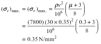
For a wheel at 152.4 mm in diameter & 30,000 rpm:
p = 7800
u = 0.3
v = peripheral velocity in m/s.
I get a peripheral velocity of 239.4 m/s and stress of 184.4 N/mm2 or 26,700 psi, well below the 150,000 psi tensile strength for 4340 but only a safety factor of 5.6.
I also found a section in the Machinery's Handbook titled: "Centrifugal Stresses in Flywheel Rims":
In general, high speed is desirable for flywheels
in order to avoid using wheels that are unnecessarily large and heavy. The centrifugal
tension or hoop tension stress, that tends to rupture a flywheel rim of given area,
depends solely upon the rim velocity and is independent of the rim radius. The bursting
velocity of a flywheel, based on hoop stress alone (not considering bending stresses), is
related to the tensile stress in the flywheel rim by the following formula which is based on
the centrifugal force formula from mechanics.
V = square root (10 × s) or s = V squared ÷ 10
where V = velocity of outside circumference of rim in feet per second, and s is the tensile strength of the rim material in pounds per square inch.
This for a one piece wheel which is what I'm using.
My surface speed at 30K will be 785.4 ft/sec so the minimum tensile strength with a factor of 10 works out to 61.7 ksi.
Ya, I know I'm thinking bigger on the wheel than what's been done in the past. Most information you come across states you want a run up time around 10 -15 seconds, but they don't say what rpm range that is for. A car engine would probably run between 1-8,000 rpm so that's about the 500 rpm/sec Performance Trends talks about. For a nitro motor it's more like 15-30K so a run time of 30-50 sec. is more like it. Also, I'm hoping to get smoother curves and more accurate data, I've heard lots of issues with data spikes from you and others. Don't know if it'll work, the 1/4" flex cable "fuse" might twist in two the first time I open the throttle!
I'll finish turn the wheel between dead centers (thanks Rudy) so it'll be accurate but also so that I can easily put it back on the lathe and trim the diameter if needed.


