Run in stand/dyno build.

Intlwaters

Help Support Intlwaters:

This site may earn a commission from merchant affiliate links, including eBay, Amazon, and others.
"Sounds great! I will start a dyno build in the new year using the information you have provided here and also all the information Jim Allen shared. "

Ricky, you might also be interested in my dyno article in the NAMBA Propwash. Mike Bontoft and I have mado over a thousand runs on it over the years.

Lohring Miller
Much very good info in this article. I used it a lot when building my dyno. Mr. Lohring also helped me by emails when sizing the inertia wheel.
 
My toy dyno.....many, many hours of fun....so far.
With a hysteresis torque brake and/or an inertia wheel, simply shift between the two.

Charles
 

Attachments

  • My Dyno 003.JPG
    My Dyno 003.JPG
    569.9 KB
Last edited:
Mechanically, hysteresis and eddy current brakes are very similar. The basic difference is the material that the rotor is made of.
Hysteresis rotors are made from ferrous materials (iron...steel...ect). Eddy current brake rotors are made of non-ferrous materials (aluminum...brass...ect). The scientific explanation of each type gets very involved.

The hysteresis brake amount on my dyno is controlled by varying the DC voltage applied to the electro magnets by turning the dial on the control panel. It is also linear.

When I built my dyno I could not find a brake unit to match my requirements so I had to build my own. There are many more units available now, especially for small loads, and there are probably some that could be used for our applications.

The control panel is mine also....

This is my third small engine dyno. My dyno that I have now has been a work in progress for a lot of years. After I play with it for a while, I take it apart and update it to try to make it more consistent. It is getting closer.
 
Sorry but eddy current brakes or couplings will not work with their rotors or pole pieces made out of non ferrous materials. They must be some form of ferrous metal, as in steel, or layers of steel sheets cut into the rotors of field parts. Cast iron does not work and neither does most form of stainless. For them to work they must have some form of teeth to be able to pass the magnetic force thru , which is the eddy currents.
 
Wikipedia: Eddy Current Brake

Mechanism and Principle

Mechanism and principle[edit]

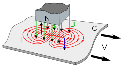
A metal sheet moving to the right under a magnet, illustrating how a linear eddy current brake works. In this drawing the magnet is drawn spaced apart from the sheet to reveal the vectors; in an eddy current brake the magnet is normally located as close to the sheet as possible.

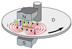
A circular or disk eddy current brake
An eddy current brake consists of a conductive piece of metal, either a straight bar or a disk, which moves through the magnetic field of a magnet, either a permanent magnet or an electromagnet. When it moves past the stationary magnet, the magnet exerts a drag force on the metal which opposes its motion, due to circular electric currents called eddy currents induced in the metal by the magnetic field. Note that the conductive sheet is not made of ferromagnetic metal such as iron or steel; usually copper or aluminum are used, which are not attracted to a magnet. The brake does not work by the simple attraction of a ferromagnetic metal to the magnet.
 
^^^ Wasn't sure how this was going to play out. But, at work we have NDI (Non-destructive inspection) done on aluminum components utilizing Eddy Current. Interesting stuff guys. I know enough about it to be dangerous - project engineering is my trade - I rely on the experts for NDI help.
 
Mark, sometimes it is very easy to get eddy current, hysteresis, magnetic coupling, ect mixed up since many companies with different applications are using different terminology to describe their products and systems.

Charles
 
Last edited:
I built a brake dyno with dead computer hard drive disks and magnets. I was thinking of it as a run in dyno for smaller engines and/or electric motors, but its a lot harder to use than our inertial dyno.

Lohring Miller
 

Attachments

  • P1010229.JPG
    P1010229.JPG
    666.9 KB
  • P1010232.JPG
    P1010232.JPG
    692.7 KB
  • P1010233.JPG
    P1010233.JPG
    698.8 KB
Well I will not argue with you but you need to go back to school on this one. Eddy currents can not do their job passing thru non ferrous metals. What you have posted in the second statement that you read in wikipedia on the non ferrous is not correct. Passing non ferrous metals thru a magnetic field will do nothing but look at you.
I have a dyno that I put together about 25 years ago using a 200 hp eddy current coupler. I locked the output shaft with a torque arm connected to a load cell. I also installed a encoder to the input shaft. By coupling a electric motor to the input shaft, I can measure the torque, rpm and then convert it to horsepower. The math is very simple. It is Ft-Lbs. x rpm divided by 5250 = Horsepower.
I have been in the electric motor business for over 50 years. So I do know a little about how eddy currents work in rotating electrical equipment.
 
Mark,

A rail gun fires an aluminum (usually) slug and works on essentially the same forces we are discussing here. All metals are affected by magnetic force, not just ferrous.

Thanks. Brad.
Titan Racing Components
BlackJack Hydros
Model Machine and Precision LLC
 
Isn't this kind of the same principle that maglev trains and catapults on the new aircraft carriers work?
I imagine if it can launch an aircraft, loading a small engine would be a piece of cake...
 
A dirty one just for Ray, lol:

full


I was getting those long stringy chips so my Consigliere told me to stop being such a wuss and crank it up:


Well I will not argue with you but you need to go back to school on this one. Eddy currents can not do their job passing thru non ferrous metals. What you have posted in the second statement that you read in wikipedia on the non ferrous is not correct. Passing non ferrous metals thru a magnetic field will do nothing but look at you.
I have a dyno that I put together about 25 years ago using a 200 hp eddy current coupler. I locked the output shaft with a torque arm connected to a load cell. I also installed a encoder to the input shaft. By coupling a electric motor to the input shaft, I can measure the torque, rpm and then convert it to horsepower. The math is very simple. It is Ft-Lbs. x rpm divided by 5250 = Horsepower.
I have been in the electric motor business for over 50 years. So I do know a little about how eddy currents work in rotating electrical equipment.

I stopped arguing with people when I finally convinced her to leave......I kept the dog.....he does not fuss, he does not argue, he does not drive so I do not have to buy him a new car, he does not need fancy jewelry, he does not need a fur coat, he already has one and he meets me at the door every day with his tongue hanging out and his tail wagging.
 
Last edited:
I built a brake dyno with dead computer hard drive disks and magnets. I was thinking of it as a run in dyno for smaller engines and/or electric motors, but its a lot harder to use than our inertial dyno.

Lohring Miller

Mr. Lohring, one of the primary differences between your brake and mine is I use electric magnets instead of you using permanent magnets. I just vary the DC voltage to the electric magnets for the load control. It is very precise.

I ended up using the torque brake mostly for engine break in.........The inertia wheel gives much more information about the engines HP and torque.
 
I ended up using the torque brake mostly for engine break in.........The inertia wheel gives much more information about the engines HP and torque.

To me the important thing is did you guys get any useful information that translated to what you were doing "in the field"?

I'm not building this thing to make fancy graphs, I want to see some chit!
 
Going to try and put this in simple terms. For eddy currents to work you must have some sort of design that will create like a coil or coils in the part you are try to excite. As you can see in the picture you have stator laminations and stator slots. In these slots there is a winding. In this winding the teeth that we call that face the rotor laminations will have a north and a south all away around the stator. In the rotor slots there are what we call bars. They can be aluminum, copper or brass. Copper being the best and aluminum being the cheapest. These bars must be connected on each end. It is what we call end rings. If one or more are not connected or broke to the end rings will cause the rotor to fail get hot at that spot and the motor will not make hp. When the teeth of the rotor pass the teeth of the stator the eddy current will pass it's magnetic force into the rotor bars. when this happens the bars start to change from north to south or south to north. The rotor bars are like a winding inside the rotor By the polarization of these bars causes the rotor to turn. or what we call chasing itself. All laminations are steel. By locking the rotor in this picture will create a eddy current brake. But you would not have the control because this is a AC type of design. We would have to redesign the winding to work for that type of eddy current brake.
Eddy current couplings or brakes are a more simple form of this. There must be laminations of steel or steel bars with some form of winding of copper, aluminum, or brass to pass the eddy currents. You can not pass a plate of aluminum thru a field and make it react.


figure-1-stator-and-rotor-laminations-1.gif
 
Terry,

Sorry for helping hijack your thread, but I think this information is useful for those who might build their own dyno...

Mark,

Rail Gun

Again.... A rail gun fires a non-ferrous projectile. That projectile is "reacting", pretty impressively, I might add, to nothing more than the presence of a magnetic field. The only requirement on the material is that it be conductive. Copper would most likely be the material of choice if it weren't so damned dense. I believe aluminum is used because it is fairly electrically conductive and is light enough to be accelerated very rapidly.

The "drag" in Charles' dyno is the analog of the projectile in a rail gun.

If I'm not mistaken, it is the copper windings that are "reacting" to the magnetic field in an induction motor, and the steel frame is simply there to carry them.

Thanks. Brad.
Titan Racing Components
BlackJack Hydros
Model Machine and Precision LLC
 
Brad, Rail guns are what we call a linear motors. Linear motors have been around for years. The same as maglev trains or electric catapults on naval ships. There is more to that projectile than a block of aluminum.
Another way of looking at is to take the drawing I showed and cut it to lay flat. This would be a linear motor.
And you are right as to the windings make the magnetic field but it must be transfer to a pole piece to be able to create workable device. This is how an electro magnetic is made. You take insulated wire and wrap it around a steel pole.
We are fixing to rewind a large electro magnetic in a couple of weeks. I will post pictures of the pole pieces and the winding of the unit. This magnetic is used to remove scrap steel from a conveyor belt and transfer it to another conveyor belt in a scrap yard. The whole magnetic is only 14,000 lbs. in weight.
 
Back
Top