Propeller Cupping????

Intlwaters

Help Support Intlwaters:

This site may earn a commission from merchant affiliate links, including eBay, Amazon, and others.

Jim Allen

Well-Known Member
Joined
Jun 7, 2005
Messages
1,622
Any cupping of a propeller blade that is perpendicular to the propellers pitch line can be measured accurately with a pitch gage. However, cupping that is done which is perpendicular to rake lines cannot be measured with a pitch gage. Sometimes the two types of cupping can overlap on each other.

How do ball type devices, which can only add cup in one area, add cup to the entire trailing edge of a propeller? How is cupping that is done perpendicular to rake lines measured? If cupping across rake lines cannot be measured, is this process done with an "eye ball check"?

The photos posted were taken from Quicksilver Marine's book "Everything You Need To know About Propellers".

Jim Allen
 
The last line in the section seems relative to the topic. Why would it only benefit a sub surface prop and not a surface piercing prop?
 
I dont run sub surface though watching all the fe motors and esc's burn up trying to would be nice!!!!! Theres nothing like a good book! Ill be ordering my copy today!!!!!!!. A cylindrical cupping anvil seems more appropriate huh?
 
Last edited:
The last line in the section seems relative to the topic. Why would it only benefit a sub surface prop and not a surface piercing prop?
Trailing edge cupping helps both types of props, sub surface & surface piercing. It does not work on submerged props. It looks from testing thus far that a propeller a with Barr cut & cupping of the entire trailing edge works best. Testing in gas boats is done with an electronic tach and the Stalker radar gun. Testing in the nitro boats is done with an audio tach & radar gun.
 
Sorry, I was reading in a rush..

The last line in the section seems relative to the topic. Why would it only benefit a sub surface prop and not a surface piercing prop?
Trailing edge cupping helps both types of props, sub surface & surface piercing. It does not work on submerged props. It looks from testing thus far that a propeller a with Barr cut & cupping of the entire trailing edge works best. Testing in gas boats is done with an electronic tach and the Stalker radar gun. Testing in the nitro boats is done with an audio tach & radar gun.
 
"It looks from testing thus far that a propeller a with Barr cut & cupping of the entire trailing edge works best. "
This sounds like a good combo. I am curious as to what the book says on pages 17 and 18 about rake and the effects of cupping perpendicular to the rake lines. It's clear that cupping increased pitch, how is lift adjusted in a prop? Specifically, take lift out of a 1400/1600 or H-series, and add lift to an X-series, which seems to have less lift?

Mark.
Propeller lift is effected most by the amouint of propeller blade rake. I am told that cupping in the right area & back cutting can change blade lift. I have never tested this. I would be happy to fax pages 17 & 18.

Jim Allen
Thanks Jim! I'll pm you about faxing.

Mark.
 
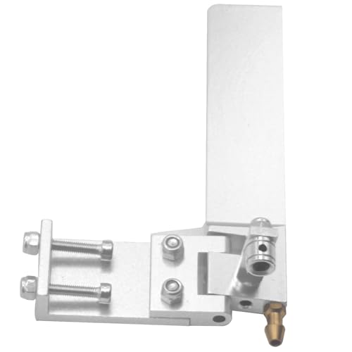
Here is something you might be interested in Mark. My pitch gage does what this one will do except the arm rotates instead of the prop rotating. I mounted a 2.000" travel indicator where the probe is mounted. Moving the probe in & out while the prop was stationary allowed me to read rake amounts. Rotating the probe allowed me to read pitch amounts. You could make pitch & rake amounts between blades as close as .005". I only take time to read pitch amounts now.

http://www.proptracker.com/default.asp

Jim Allen
 
Last edited by a moderator:
Mark,

The fax number you e-mailed to me doesn't work. I have a second copy of the book that I would mail to you if you will pay the postage.

Jim Allen
 
Jim, because of the rounded tip of the 1600 series or similar propeller how would you go about cupping the trailing edge all the way to the tip without intersecting the rake lines? is that possible? The x series seems like the easiest and best series prop to mod if you dont want to get into any un-measurable stuff. Im afraid to say it Jim but yes Im afraid many do eyeball it. Thats very hit or miss but when it hits id make a mold. I too prefer the method of "knowing" exactly whats going on. Without that I really dont know how youd map a propeller????? Also based on this info a "de cup" might be a useful fe prop mod if you want a full bladed higher rpm prop? Does the bar with the cup help bring the k's back up?In your opinion how does blade area play into all this?????

I would really love to see a thread on your pitching technique. John Beardslee touched on the topic of pitching blocks but with the photos you have you can give an explanation with photos. I couldnt make much sense of it until I saw the photo.It explains what would be your method of changing the pitch.

Hugh
 
Last edited:
Wow! A lot of questions here. I think that would be possible with the 1600 series Octura props. Let's use the popular smooth running 1667 oval prop as an example. If you were to cup the entire trailing edge for 1/4" in width, a very small amount of the rounded tip will be involved. The problem with a blade such as this is what will take place as you move down towards the root. You cannot make the trailing edge pitch the same down to the root of this blade because at root the blade cannot be bent, even if it has been annealed. A Barr cut with a 3/8" ball nose mill will allow the blade to be easily cupped to 7.5" over the entire trailing edge. Also the Barr cut will allow the leading edge pitch to be raised to 5.5". The pitch progression is 36.4%. The full blade area on a gas rigger turning 22,000 rpm goes approximately 75+ MPH on the oval.

Prop mapping would require a pitch gage capable of measuring leading edge, trailing edge & rake angles on any blade. It would be similar in design to Prop Scan's Gage. The gage I use can do this when I mount a 2.000" travel .0005" dial indicator to the rotating arm. The indicator can be rotated in a 72 deg arc, & it can slide in & out on a slotted keyway.

The larger the blade area the less the amount of cup needed & vice versa. Everything is a trade off.

Jim Allen
 
Here is something you might be interested in Mark. My pitch gage does what this one will do except the arm rotates instead of the prop rotating. I mounted a 2.000" travel indicator where the probe is mounted. Moving the probe in & out while the prop was stationary allowed me to read rake amounts. Rotating the probe allowed me to read pitch amounts. You could make pitch & rake amounts between blades as close as .005". I only take time to read pitch amounts now. http://www.proptracker.com/default.asp Jim Allen
That full size device looks amazing. Sounds like you have done a very good duplication and can get a good number on rake and if you bend perpendicular to the rake direction then it can be quantified. Nice. I would cover the postage on that book and appreciate the offer, sorry about the fax.

I know that working with props gives understanding of these variable changes and that a few guys here have great experience about doing it. I'm interested in getting some of the variable linked to a direction of operation. Bend this way, prop does this. Cut this way, prop does this. Then you can link up the bends and cuts to fit your prop to the boat your working with, or even developing. I also have to say that there certainly are a lot of excellent props available for purchase these days.

Mark.
 
So the barr cut in fact serves a slightly different purpose than a backcut when you use it in conjunction with adding TE pitch. A back cut simply removes trailing edge or (boost pitch) while the barr can relieve the blade from root so you can cup the TE or it just removes a fraction of the boost pitch when the barr cut is done as the only modification by itself?
 
So the barr cut in fact serves a slightly different purpose than a backcut when you use it in conjunction with adding TE pitch. A back cut simply removes trailing edge or (boost pitch) while the barr can relieve the blade from root so you can cup the TE or it just removes a fraction of the boost pitch when the barr cut is done as the only modification by itself?
I don't know how to answer, so maybe what you have said is correct. The only props that I back cut from the tip down to the root were used for straight away running. The trailing edge pitch was corrected after. These were 1967 & 2267 two bladed props. Typical leading edge pitches of 5.375" & cups amounts of 8.125" at 28,000 gave speeds over 95 MPH. 2170 props with reduced diameters of approximately 2.500" & texas cuts in pitches of 5.250" X 6.750" at 30,000 gave speeds over 100 MPH. I never tested a Barr cut on a straight away prop.
 
A 2267 spun @ 28k pretty impressive Jim! A 2163.5 mm texas cut @ 30,000 sounds devastating! I assume those props were pulled on your scratchbuilt .90's? Thank you very much for sharing your knowledge here on IW.Lord how can I get one :( ..

Hugh
 
Last edited:
A 2267 spun @ 28k pretty impressive Jim! A 2163.5 mm texas cut @ 30,000 sounds devastating! I assume those props were pulled on your scratchbuilt .90's? Thank you very much for sharing your knowledge here on IW.Lord how can I get one :( ..

Hugh
I don't claim to know everything about surface piercing propellers, but if I find some thing that is working, I can duplicate that prop exactly with my prop gage & get the same results.

Jim
 
Jim here is a running log of a ABC2818 in my SGX with a 1.01 in it full race setup.

this was a death run as you can see from the temp. could not cach up to the pipe with the needle.

with 300000RPM behind this all I can say is WOW. Give it a spin I thing you will like it.

On the next build I am setting the pipe for 260000RPM will see if it will live.

David
David, exactly what failed in the motor? How can you run the engine at it's mechanical limit & expect it to survive? No amount of fitting, exotic timing, exotic fuel, special pipe, etc. will mean anything until you find a way to make the engine mechanically, 100% reliable at the RPM you want to run at. With all highly stressed mechanical devices there must be a cushion built into the design.

Jim Allen
 
Back
Top