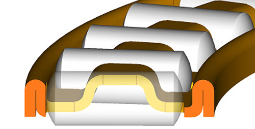
Bearing cage material

Intlwaters

Help Support Intlwaters:

This site may earn a commission from merchant affiliate links, including eBay, Amazon, and others.
Jim,

Since you are running an all steel front end, what are your thoughts on replacing the rear ball bearing with needles? The front bearing would have to remain a deep grove BB to handle any thrust forces. You would have to case harden the crank and housing, but you would expect to see greater load handling on the rear although at possibly greater friction. Thoughts?

On the topic of cantilevered versus three piece crank: Hypothetically speaking, if a three piece crank was aligned with the same tolerances as a cantilevered crank, the friction and stability should be superior over the cantilevered? If there were no other packaging considerations, what are the pro's and con's of the cantilevered versus 3 piece?

-Tyler
 
Tyler,

Lets discuss a full complement type needle bearing first. The number one problem with any full complement roller bearing operating at a high RPM is the helix angle the rollers develop as the assembly rotates. Caged roller assembly types (typically M or A type cages) are better at controlling the helix angle of the rollers. However, because they guide the rollers above & below their center line, a small helix angle that is not parallel to the axis of rotation will still be present. The solution to this problem would be a machined retainer which guides the rollers along their center line from end to end. I use this type of a machined hardened steel retainer in the steel connecting rods of my engines. (photo below)

The failure of most ball bearings in nitro engines that use a cantilevered type crankshaft is due to an insufficient amount of radial clearance. A C-3 (.0002" to .0005"), C-4 (.0005" to .0008") or C-5 (.0008" to .0011") ball bearing my not have sufficient radial clearance if the interference fit in the housing is to tight. The same thing happens if the housing is made off a rigid material. The inner & outer races of radial ball bearings are NOT designed to be able to support themselves. This is why in high performance engines the crankshaft should be pressed into the inner race & shrunk into the aluminum housing.

I agree with your second paragraph in part. As I stated, you want the crankshaft to be pressed into the inner race of the bearing in question & you want the bearing to be shrunk into it's housing. This could be done with either type of crankshaft. Three piece crankshafts should be more rigid & stronger, providing they are of adequate size. If the cantilevered crankshaft's diameter in my .90 cu in (15 cc) engine is .5906" (15 mm), why is the crankshaft in a 30 cc gas engine .4724" (12 mm)? Does this small diameter cancel the advantages found in a three piece crankshaft? There is one advantage when a cantilevered crankshaft is used in a single cylinder engine. The entire back end of the engine is available for the use of the induction system.

JA

connecting%20rod%20025.jpg
 
Last edited by a moderator:
Thanks for the insight Jim,

Some years ago I was ambitious and started designing my own 26cc motor as I had a great mentor who spent 30 years designing 2-stroke engines for Yamaha, Stihl and others. Although I had no means of affording the engine it was a good design exercise and still needs to be finished.

We based the design around a scaled down 50cc motoGP engine. One of the limiting factors was the small end and large end bearings for the rod. We used the smallest available INA bearings recommend. INA/*** has a special document for roller bearings for connecting rods in 2-strokes.

We went with the full circle crank, slugged for balance and zimmerman disk. The dimensions and proportions are closer to a larger bike 2-stoke not the compact Zenoah based designs.

Someday I would love to sit down with you and get your opinion on the design thus far.

Tyler

Some files attached of my design.

TRG 260 crank_12mm.JPG

INA *** Needle Bearing CrankPin tpi94.pdf

TRG 260 crank_12mm.PDF

TRG 260 crank_12mm TDC - Sheet1.pdf

TRG 260 crank_12mm BDC - Sheet1.pdf
 

Attachments

  • INA *** Needle Bearing CrankPin tpi94.pdf
    626.4 KB
  • TRG 260 crank_12mm.PDF
    982 KB
  • TRG 260 crank_12mm TDC - Sheet1.pdf
    30.7 KB
  • TRG 260 crank_12mm BDC - Sheet1.pdf
    29 KB
This end view drawing of a machined retainer demonstrates how the rollers are guided along their center lines & not above & below their center lines. The drawing also shows how two rollers can be placed side by side in one window of a machined retainer. Machined retainers made from C-350 Maraging steel are hardened to 60 Rockwell "C" & they have a 350,000 lb tensile strength. Adding an extra roller to each window greatly increases the load carrying capacity of the assembly without any loss of rotational speed or an increase in friction. Notice the pie shaped piece of the retainer section & notice how thin (.027") the pie shaped section is at the center line of the rollers. This reduction in the retainer's mass reduces its inertia which helps reduce roller sliding.

JA

.625 bore barrel carburetor on QD 209.jpg

002_2013-07-04.jpg
 
Tyler,

I have proven beyond any doubt that in very high RPM nitro & gas engines, "no roller assembly or bushing material" is needed in the upper end of the connecting rod. The selection of the metallurgy used for the connecting rod & the wrist pin make this possible. Doing this lengthens the connecting rod (reduced angularity), raises the wrist pin hole up higher in the piston (reduced piston rocking) & reduced piston weight.

I am sure after thousands of dyno tests that there is a better induction system than any induction valve presently used. This is why I prefer a cantilevered type crankshaft over a three piece crankshaft for a single cylinder engine.

JA

.625 bore barrel carburetor on QD 020.jpg
 
Jim,

On the topic of caged needle bearings, in your design do you have a line of contact between the roller and cage? Compared to a stamped cage which has two to three points contacts or other billet cages which look like they have bumps to minimize the contact surface.

news20070227_2.jpg


2-c.jpg


I know on the topic of induction systems, there seem to be many good solutions and some like the bell or drum favor the cantilevered versus the disk which is favored by the three piece cranks. If tether cars are the upper echelon of model engines, the disk still seems the preferred method even for cantilevered cranks. How much of that is packaging versus other performance factors I don't know.
 
Tyer; I can tell you that the bell valve is real good. I have run one on. the tether car. The only bad side is it is a bitch to make. I got to thank Jim Allen for his bell valve drawings. J.
 
Tyler,

Your first illustration shows why the rollers remain in place when a stamped roller retainer assembly is removed from the engine. The rollers can be snapped in & out of this assembly with a small amount of force. Your second illustration shows a machined cage that is relieved at the end points because the rollers used do not have a radius on their ends. This means the retainer material in between each roller must be thicker to allow for a relief on both sides. This decreases the number of rollers possible & makes the retainer unnecessarily heavy.

Tether cars are subjected to high "G" forces (maybe 8 or 9) when running at speed & this my make it impossible to use some types of induction valves. Jack O'Donnell is the only person that I have knowledge of who used the bell valve in a tether car. These forces are not present in a model boat.

The photo shows the retainer with two rollers in each window that is in the print. It is pulled out slightly to make the parts visible. The crank pin's OD is .3281" & there are 16, .0627" rollers used. The rollers used in this assembly have a radius on each end which allows a radius, without any relief, in every corner of the retainer. This makes the retainer much stronger & lighter in weight than the design in your second illustration. The rollers in this type of retainer are guided along their center line only. Look carefully at the two drawings & the photo.

JA

pict0010a.jpg
 
I outlined the issues and Jim's solution in the April 2012 Propwash article Big End Blues. I think the big end is the main limiting factor in our gas engine crankshafts. I personally had a cage failure in an M&D cast cylinder engine that I ran regularly over 20,000 rpm for several seasons. I've also seen blue big ends in Zenoahs that power riggers. I remember being surprised a long time ago seeing the tach registering over 20,000 rpm at the end of the straight in a heat racing rigger. I bet that happens frequently in the fastest riggers today.

Lohring Miller
 
So the key to the big end seems to be rollers with radiused ends, two rollers per window and a solid retainer. Jim, I don't see any eyebrows in the big end for oil. Are there saw slits or do you just have enough oil? Also the I-Beam rod is not profiled on the leading edges for drag. Pics of the CMB35RS rod below which has the profiled edges and eyebrows. Once we figured out the tolerance on the 35RS motor it has been very reliable. I consider it a decent design.

Is the bell valve an issue in the tether cars due to the higher imbalance of the bell itself at least compared to a disc or drum where the mass in more centralized?

I have not read the FMV story in a while, but wasn't one of the issues with the bell induction the lack of oil in the induction stream not hitting the big end? Or was this solved?

TG

IMG_5419.JPGIMG_5424.JPGIMG_5428.JPG
 
Yes, a machined retainer that can be hardened with radii on the roller ends & in the retainer's corners. The metallurgy of the various parts is very important also! The VascoMax C-350 maraging steel selected for the retainer has a simple, precipitation aging, low temperature heat treatment. This low temperature heat treatment (900 to 925 deg F for 4 to 6 hours) allows the steel to be hardened without any distortion. A shock resisting tool steel (AISI S-7) is used for the connecting rod. After hardening & tempering the entire rod in a fixture, the wrist pin hole & the crank pin hole are align ground so that they are parallel to each other in two planes. Doing this allows very close tolerances to be used in the top & bottom end. The bottom end of the rod has two oil slots which are staggered. The top end has one oil slot. I have tested many types of profiled rods in various sizes of engines without seeing any improvement in engine performance. The "I" beam section of the rods in my gas engines are .356" wide X .156" thick. The relieved section on both sides to make the rod a true "I" beam is .055" deep on both sides X .271" wide. This means the thickness in the middle of the "I" beam is .046". The nitro engine's rods in this same area are .031" thick. These numbers are possible because the entire rod is hardened & tempered. After heat treatment the entire rod has a 315,000 lb Tensile strength at 57 Rockwell "C". July - August, 2006, Model Engine Builder magazine has some detailed pictures of the fixtures required to machine a rod such as this.

The bell valves that Jack & I are referring to are fully balanced. This cannot be done with any other type of induction valve! The bell valve has several unique features, besides being fully balanced, that are not found in any other induction valve. It is totally unaffected by the crankcase's pumping action & it gives the largest time area numbers possible. The FMV engine did not use a bell valve, but it is the first engine to use a steel front end that is the same in design as the front ends I use.

Jim Allen

PICT0013.JPG
 
Last edited by a moderator:
Beautiful workmanship, Jim. Being a machinist for almost 50 years I can appreciate the time and effort that it took to make these pieces. And the best part is that they work!

Dick Tyndall
 
Back
Top