1994 Hydrofest Smokin' Joe's ML Boatworks build

Intlwaters

Help Support Intlwaters:

This site may earn a commission from merchant affiliate links, including eBay, Amazon, and others.

JakeZella

Member
Joined
Oct 15, 2024
Messages
8
Hello,

I am embarking on my first build, this will be my first hydro build, and first boat build overall. For the build, I have chosen the ML Boatworks 158 extreme kit to build the 1994 Hydrofest Smokin' Joe's U-10. From what I understand, this is one of the boats that has had a lot of variance in the painting and design race to race, and getting it accurate to that exact race may be difficult.

I have placed orders for the Cowlings and Wings from RC Boat Company, as well as the plans from Newton Marine. I have a jig built out to match the width of the kit from ML, and have started to work on getting everything sanded smooth and mating properly. I intend to update this thread as the build progresses. Any advice from those that have built this hydro in the past would be greatly appreciated! Taking a look at the parts laid out, it looks like the Cowling area will be a lot of work to get correct, and I do not see any information on how to do the winglets on the rear transom, but I have hope that these will be a little clearer once I get the Newton plans.

Thank you to all of you that have made build logs in the past, as reading through them has been extremely helpful in getting my head wrapped around this build!

Thank you,
Jake Zella
 

Attachments

  • Jig.jpg
    Jig.jpg
    178.7 KB
  • Parts.jpg
    Parts.jpg
    229.6 KB
Wax paper is your friend. I have glued a few boats to jigs. Not fun getting it off.

I also have built the the front of the jig so it tapers up. Usually cut in 3 sections. Center cowl and either side. I also use some #4 screws to hold down the bottom sheeting.
Mike
 
Last edited:
Wax paper is your friend. I have glued a few boats to jigs. Not fun getting it off.

I also have built the the front of the jig so it tapers up. Usually cut in 3 sections. Center cowl and either side. I also use some #4 screws to hold down the bottom sheeting.
Mike
For the gluing the winglet on. If you glue a block of wood to the inside of where the skin will be glued on, then shape it so the skin can cover it. After the skin is glued on you can make a winglet out of wood with a tenon made into the winglet. Then draw a rectangle on the outside of the skin where you want the winglet to go like a mortise. Drill several holes on the inside of the rectangle and take a wood chisel to clean the inside up so the tenon on the winglet is snug. Then you can glue the winglet into the mortise. Hear is the link for how to cover the boat with fiberglass. Fiberglassing tutorial with Greg Hahn model aviation magazine YouTube. After I cover the boat with the fiberglass and a second coat of epoxy I got some glazing putty like a autobody guy uses and put a thin coat over the fiberglass to make it smooth and even after sanding. If you want me to show you a picture of what a mortise and tenon look like I can try to upload a picture if I can figure out how to do it.
 
Generally speaking, you want to keep fiberglass on a wood hull to a minimum. Some joints can benefit from the extra strength but, normally, fiberglass is just unwanted weight. You also have to consider that fiberglass will require filler to hide the fabric. That adds more weight, that is unless you don't care if the weave shows through the paint. Fiberglass can also make repairs harder since you will need to cut through or remove the glass to repair damage. Two things to remember:
  • if you race, accidents will happen, it's just a matter of when
  • hydroplanes can and will blow over
In either case, you have to expect damage. Why make it harder to repair than it needs to be?
Just my two cents
If you fiberglass the hull it will make it stronger and there will be less damage if you get into a accident and a hull that's a little heavier won't blow over as easily and can be easier to drive and go through when there is rough water
 
Wax paper is your friend. I have glued a few boats to jigs. Not fun getting it off.

I also have built the the front of the jig so it tapers up. Usually cut in 3 sections. Center cowl and either side. I also use some #4 screws to hold down the bottom sheeting.
Mike
Thank you for the heads up, I picked up some wax paper for exactly this reason! Last night I was able to get the measurements taken for the critical dimensions for the first part of the build, and started laying up the stringers and framing what will be the bottom of the tunnel.

A bit more about the build, I am planning on this being an FE build at the end of the day. Upon review of the NAMBA rules, it looks like they are a bit more strict than IMPBA. I was previously planning on 10S, but have adjusted this to 8S for NAMBA. The plan at the moment is to get a NEU 1527 1.5Y mated to a Castle XLX2 esc, from what I have gathered this should be a relatively solid power plant, and raceable. If anyone has recommendations I am all ears. I am NAMBA district 20, and based out of Colorado, our boat scene here is very much not the largest from what I have seen, but we do have some people up here. I don't believe that we currently run an Unlimited Class here right now, if that is incorrect, please correct me on that! The build will mostly be for fun, but I do have hopes to race it if an opportunity arises.
For the gluing the winglet on. If you glue a block of wood to the inside of where the skin will be glued on, then shape it so the skin can cover it. After the skin is glued on you can make a winglet out of wood with a tenon made into the winglet. Then draw a rectangle on the outside of the skin where you want the winglet to go like a mortise. Drill several holes on the inside of the rectangle and take a wood chisel to clean the inside up so the tenon on the winglet is snug. Then you can glue the winglet into the mortise. Hear is the link for how to cover the boat with fiberglass. Fiberglassing tutorial with Greg Hahn model aviation magazine YouTube. After I cover the boat with the fiberglass and a second coat of epoxy I got some glazing putty like a autobody guy uses and put a thin coat over the fiberglass to make it smooth and even after sanding. If you want me to show you a picture of what a mortise and tenon look like I can try to upload a picture if I can figure out how to do it.
Thank you for the advice on the winglets, as well as the recommendation to take a look at the fiberglassing tutorial. That will be a huge help! To Hydro's point, I am not sure if I will be glassing the exterior or not, but I will for sure be reinforcing the Transom and interior of the sponsons with fiberglass to ensure long term survival. A question to both of your points, what is the average weight that 1/8 scale FE should be around? Too heavy and you're wasting speed pushing the boat, and slower to recover, but lighter I would think you'd increase risk of blowover, and spinning out in turns. I am not sure where that line is though.

Got the base screwed on the jig with some #4 screws, added washers to make sure the pressure's more spread out. I was able to use some 123 blocks and a lot of clamps to get the first bit of glue laid.
 

Attachments

  • Clamps1.jpg
    Clamps1.jpg
    249.3 KB
  • Clamps2.jpg
    Clamps2.jpg
    304.1 KB
Thank you for the heads up, I picked up some wax paper for exactly this reason! Last night I was able to get the measurements taken for the critical dimensions for the first part of the build, and started laying up the stringers and framing what will be the bottom of the tunnel.

A bit more about the build, I am planning on this being an FE build at the end of the day. Upon review of the NAMBA rules, it looks like they are a bit more strict than IMPBA. I was previously planning on 10S, but have adjusted this to 8S for NAMBA. The plan at the moment is to get a NEU 1527 1.5Y mated to a Castle XLX2 esc, from what I have gathered this should be a relatively solid power plant, and raceable. If anyone has recommendations I am all ears. I am NAMBA district 20, and based out of Colorado, our boat scene here is very much not the largest from what I have seen, but we do have some people up here. I don't believe that we currently run an Unlimited Class here right now, if that is incorrect, please correct me on that! The build will mostly be for fun, but I do have hopes to race it if an opportunity arises.

Thank you for the advice on the winglets, as well as the recommendation to take a look at the fiberglassing tutorial. That will be a huge help! To Hydro's point, I am not sure if I will be glassing the exterior or not, but I will for sure be reinforcing the Transom and interior of the sponsons with fiberglass to ensure long term survival. A question to both of your points, what is the average weight that 1/8 scale FE should be around? Too heavy and you're wasting speed pushing the boat, and slower to recover, but lighter I would think you'd increase risk of blowover, and spinning out in turns. I am not sure where that line is though.

Got the base screwed on the jig with some #4 screws, added washers to make sure the pressure's more spread out. I was able to use some 123 blocks and a lot of clamps to get the first bit of glue laid.
If you fiberglass the boat you can buy 1/2 oz fiberglass from Balsa USA and to help seal the boat inside and outside even if you don't fiberglass the outside you can buy West Systems epoxy 105 resin, 207 special clear hardner for where the engine, pipe etc are at because it won't get a yellow/brown color after the epoxy ages. And me personally I wouldn't thin the epoxy in this area. And 209 hardner for everything else and to seal it and if you use fiberglass to. You can thin it out with some alcohol. When I build a boat I buy some 2" and 1" thick Blue Dow board and glue it between the frames with a snug fit and sand/file the extra off flush. It will strengthen the boat and for floatation. But I am real anal about strength from me being in construction. You can buy the epoxy off of Amazon. I don't know if you can buy it direct from the factory
 
Most boats I've seen are in the 12-14 pound range, though I've seen a few down to around 10. Lightest boat I've ever seen was around 8 pounds. My boat is a little heavier, at 14 pounds. Just to be clear, this covers all 1/8 scale boats, nitro and electric.
When it comes to blowing over, ANY BOAT CAN BLOW OVER!!!! All it takes is a good gust of wind or some chop and over you go. By building the boat heavier, it makes it less likely, but not impossible. One thing that hasn't been mentioned yet is that building a boat is a series of tradeoffs:
  • Build it lighter and it's more competitive and quicker, is easier on fuel/batteries
  • Build it heavier, it's slower to accelerate and might be able to absorb an impact better but will eat more fuel
If you're worried about strength, you can use thicker wood for the framing or add fiberglass to the structure. You will be sacrificing speed(as you stated above) and, if you race, will have to drive more aggressively to have a chance to win
On the other hand, if you want a boat that can accelerate quickly, giving you more options on how you start a heat or when you might pass someone, you might consider using thinner framing or skin panels. You risk more damage to the boat in the event of a collision or blow over but, if you're one that wants to win.....
One other thing you have to consider. How you balance the boat, the prop you use and your strut setting will also affect how the boat runs:
  • More nose heavy will cause the boat to plow and pound the water more
  • More tail heavy will add drag by forcing the boat to drag the "shoes" as well as making it more likely to blow over
  • Prop too deep or too much down thrust will result in a boat that seems nose heavy
  • Prop too shallow or not enough down thrust will result in a boat that seems tail heavy
You can adjust your boat's balance by where you place the batteries, radio gear and ESC. What doesn't work is using the rear wing to lift the back of the boat. The amount of angle needed will add a considerable amount of aerodynamic drag, slowing your boat
 
I sheet decks with 1/32 ply. I usually lay on my decks with some 1oz cloth. It is lite this way. Over time the ply can crack. The cloth helps with this. 1oz does no leave the surface very porous. I usually go over it with palm sander and than lay on a heavy primer coat. Sanding most of that back off. Works great.
Mike
 
Had a busy weekend, I was able to get almost the entire center section complete! I have received word from RC Boat Company that the Cowling and fiberglass parts should be arriving soon! I have 2 more spine stringers to complete on the center section with the exception of the nose (will be fit to match the parts from RC Boat Company), then moving onto the Sponsons.

I found out once setting everything up before gluing that the weight I had on hand wasn't quite enough to get the frame to lay perfectly flat, so enjoy the small library holding the framing to the bottom sheeting.

I would like to give a huge shoutout to Mike from ML Boatworks, as this kit has been extremely easy to assemble so far, well labeled, and the tolerances of the laser cut pieces have been fantastic.

Thank you all for the recommendations and advice so far! This has been a huge help! I am still waiting on the plans from Newton, do they show mounting for Prop Shaft and Rudder locations, or is there a standard "Common" mounting location that people use? Looking at photos, I cannot quite tell if the centerline of the hydro is what dictates the location, or if it's the centerline of the cockpit (SJ has an offset cockpit) that the motor and prop shaft would be mounted in line with. The same goes with Rudder location, should this be reversed from the full size boat considering NAMBA races are CW and the full size boats race CCW?

Sorry for all the clamped together pictures below, I've had a bad habit of forgetting to snap a photo until after I've done the gluing. I will try to do better at taking pictures once I have the clamps removed to better see the progress.
 

Attachments

  • Short Ribs1.jpg
    Short Ribs1.jpg
    232.2 KB
  • Weight.jpg
    Weight.jpg
    259.4 KB
  • Spine2.jpg
    Spine2.jpg
    312.2 KB
  • Spine1.jpg
    Spine1.jpg
    286.5 KB
  • Short Ribs2.jpg
    Short Ribs2.jpg
    275.6 KB
  • Outer Center3.jpg
    Outer Center3.jpg
    264.4 KB
  • Outer Center2.jpg
    Outer Center2.jpg
    240.7 KB
  • Outer Center1.jpg
    Outer Center1.jpg
    249.2 KB
  • Framing2.jpg
    Framing2.jpg
    242 KB
  • Framing1.jpg
    Framing1.jpg
    235.8 KB
Had a busy weekend, I was able to get almost the entire center section complete! I have received word from RC Boat Company that the Cowling and fiberglass parts should be arriving soon! I have 2 more spine stringers to complete on the center section with the exception of the nose (will be fit to match the parts from RC Boat Company), then moving onto the Sponsons.

I found out once setting everything up before gluing that the weight I had on hand wasn't quite enough to get the frame to lay perfectly flat, so enjoy the small library holding the framing to the bottom sheeting.

I would like to give a huge shoutout to Mike from ML Boatworks, as this kit has been extremely easy to assemble so far, well labeled, and the tolerances of the laser cut pieces have been fantastic.

Thank you all for the recommendations and advice so far! This has been a huge help! I am still waiting on the plans from Newton, do they show mounting for Prop Shaft and Rudder locations, or is there a standard "Common" mounting location that people use? Looking at photos, I cannot quite tell if the centerline of the hydro is what dictates the location, or if it's the centerline of the cockpit (SJ has an offset cockpit) that the motor and prop shaft would be mounted in line with. The same goes with Rudder location, should this be reversed from the full size boat considering NAMBA races are CW and the full size boats race CCW?

Sorry for all the clamped together pictures below, I've had a bad habit of forgetting to snap a photo until after I've done the gluing. I will try to do better at taking pictures once I have the clamps removed to better see the progress.
The centerline for the motor will be the centerline of the offset area that the motor will be in. Like if the inside motor/engine stringer measurement is 4" then the centerline will be 2". It doesn't matter if the hull has a offset in it as long as the motor, stuffing tube and strut are all on the same centerline and square with the boat. If this is a 1/8 scale boat it's easier to put the rudder on the left side of the boat because the servo can pull the push rod and not bend rather than push the push rod and have the push rod bend. If the push rod bends it won't turn as easily. If it's a 1/8 scale boat you can buy a 1/8 scale turn fin and bracket off of Offshore Electrics. If you want to it's easier to buy a waterproof high torque servo like Savox for the rudder and they make smaller ones for the speed controller. Also who ever you get a rudder from you might see if they have a bracket and or control arm that's reversable so you can mount the rudder on the left side if it's a 1/8 scale boat. You can get the servos off of Ebay or Rattlesnake RC. I will try to get some pictures of a way to install the rudder servo and the rudder setup that might help you figure something out how you would do it your way.
 
Had a busy weekend, I was able to get almost the entire center section complete! I have received word from RC Boat Company that the Cowling and fiberglass parts should be arriving soon! I have 2 more spine stringers to complete on the center section with the exception of the nose (will be fit to match the parts from RC Boat Company), then moving onto the Sponsons.

I found out once setting everything up before gluing that the weight I had on hand wasn't quite enough to get the frame to lay perfectly flat, so enjoy the small library holding the framing to the bottom sheeting.

I would like to give a huge shoutout to Mike from ML Boatworks, as this kit has been extremely easy to assemble so far, well labeled, and the tolerances of the laser cut pieces have been fantastic.

Thank you all for the recommendations and advice so far! This has been a huge help! I am still waiting on the plans from Newton, do they show mounting for Prop Shaft and Rudder locations, or is there a standard "Common" mounting location that people use? Looking at photos, I cannot quite tell if the centerline of the hydro is what dictates the location, or if it's the centerline of the cockpit (SJ has an offset cockpit) that the motor and prop shaft would be mounted in line with. The same goes with Rudder location, should this be reversed from the full size boat considering NAMBA races are CW and the full size boats race CCW?

Sorry for all the clamped together pictures below, I've had a bad habit of forgetting to snap a photo until after I've done the gluing. I will try to do better at taking pictures once I have the clamps removed to better see the progres
Had a busy weekend, I was able to get almost the entire center section complete! I have received word from RC Boat Company that the Cowling and fiberglass parts should be arriving soon! I have 2 more spine stringers to complete on the center section with the exception of the nose (will be fit to match the parts from RC Boat Company), then moving onto the Sponsons.

I found out once setting everything up before gluing that the weight I had on hand wasn't quite enough to get the frame to lay perfectly flat, so enjoy the small library holding the framing to the bottom sheeting.

I would like to give a huge shoutout to Mike from ML Boatworks, as this kit has been extremely easy to assemble so far, well labeled, and the tolerances of the laser cut pieces have been fantastic.

Thank you all for the recommendations and advice so far! This has been a huge help! I am still waiting on the plans from Newton, do they show mounting for Prop Shaft and Rudder locations, or is there a standard "Common" mounting location that people use? Looking at photos, I cannot quite tell if the centerline of the hydro is what dictates the location, or if it's the centerline of the cockpit (SJ has an offset cockpit) that the motor and prop shaft would be mounted in line with. The same goes with Rudder location, should this be reversed from the full size boat considering NAMBA races are CW and the full size boats race CCW?

Sorry for all the clamped together pictures below, I've had a bad habit of forgetting to snap a photo until after I've done the gluing. I will try to do better at taking pictures once I have the clamps removed to better see the progress.
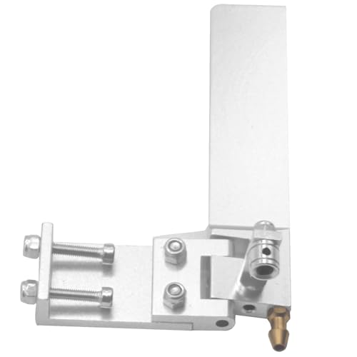
This might give you some ideas of how to mount the rudder servo and hardware. I used 4-40 blind nuts and 4-40 stainless steel pan headed allen bolts to mount the rudder servo. I drilled the holes a little bigger and sealed the inside of the holes with thin CA and then epoxy the blind nuts in. If you want to buy some carbon fiber arrows and cut to what ever length you need for a stronger push rod. I bend a 90 degree in a 4-40 push rod and cut it off long enough to go through the side of the arrow and drill a hole in the arrow and stick the 90 degree bend through the arrow and glue and fiberglass the 4-40 rod in place. If you don't know you can get all of the 4-40 heavy duty ball links and push rods ,blind nuts, aluminum servo control arm from Tower Hobbies. I got the 4-40 stainless steel bolts off of Ebay. Hopefully you can figure something out that will work for you. Also I glued a thin piece of flat aluminum on the inside of the transom where the rudder bracket mounts so the nuts won't dig into the wood.
 
Had a busy weekend, I was able to get almost the entire center section complete! I have received word from RC Boat Company that the Cowling and fiberglass parts should be arriving soon! I have 2 more spine stringers to complete on the center section with the exception of the nose (will be fit to match the parts from RC Boat Company), then moving onto the Sponsons.

I found out once setting everything up before gluing that the weight I had on hand wasn't quite enough to get the frame to lay perfectly flat, so enjoy the small library holding the framing to the bottom sheeting.

I would like to give a huge shoutout to Mike from ML Boatworks, as this kit has been extremely easy to assemble so far, well labeled, and the tolerances of the laser cut pieces have been fantastic.

Thank you all for the recommendations and advice so far! This has been a huge help! I am still waiting on the plans from Newton, do they show mounting for Prop Shaft and Rudder locations, or is there a standard "Common" mounting location that people use? Looking at photos, I cannot quite tell if the centerline of the hydro is what dictates the location, or if it's the centerline of the cockpit (SJ has an offset cockpit) that the motor and prop shaft would be mounted in line with. The same goes with Rudder location, should this be reversed from the full size boat considering NAMBA races are CW and the full size boats race CCW?

Sorry for all the clamped together pictures below, I've had a bad habit of forgetting to snap a photo until after I've done the gluing. I will try to do better at taking pictures once I have the clamps removed to better see the progress.
If you don't know on a 1/8 scale boat the turn fin mounts on the right sponson. You can mount it with blind nuts to the same way I said how I mount the rudder servo.
 
IIRC, the center offset your boat has is only .5 inch so you're only looking at .25 off center for the motor. If you use a flex shaft, you can bring the strut back to center with a couple of gentle bends if so desired.
Locating the rudder to the left or right of the prop is really a builder's decision. I tend to agree with Matt, mount it on the left side as shown below for the reasons he gave.
Click image for larger versionName:    Li21091.jpgViews:    1020Size:    114.3 KBID:    1647814
The rudder assembly shown is made by Speedmaster. Many builders use Speedmaster since you can order the assembly in several configurations.
Three things I prefer to do are:
  1. drill the mounting holes through the transom AND aluminum doubler before I epoxy the transom to the rest of the framing, preferably with a drill press, drilling the holes to the correct size for tapping the aluminum. IIRC, Speedmaster is drilled to fit an 8-32 fastener
  2. drill the mounting holes through the transom slightly larger than needed and glue in brass or stainless tubing to line the holes. This prevents water from damaging the holes and the transom from crushing over time
  3. before installing the doubler, fasten it to the back of the rudder bracket and remove the area that corresponds with the hole in the center of the bracket. This is where the rudder pushrod will go through to get to the rudder arm. After that is complete, screw the bracket and doubler to the transom and remove the wood in the pushrod hole area. Now, you are ready to install the transom. Be sure you coat the inside of the pushrod hole, in the transom, with epoxy to prevent water from getting to the wood.
You may notice that the rudder bracket is fastened using blind nuts in the picture. That is due to the fact that the boat is a 30" sport 20, not a scale boat. Something else you might notice is that the rudder itself is directly behind the engine bay side bulkhead. There are two reasons for this:
  1. this puts the rudder at the strongest part of the transom since the transom is epoxied to the engine bay bulkhead, the deck and the hull bottom
  2. using this location puts the pushrod off to the side so it doesn't get in the way as much when installing/maintaining the driveline or motor
Just went back and was looking closer at your pictures. I have to assume you have epoxied in the inner transom panel. What I said above can still be done, using a hand drill or Dremel Tool. You just have to laminate the transom panels together before doing so. As far as aligning the rudder bracket, you just need to set it on a piece of 1/16-1/8" ply to get your height where you want it
 
Last edited:
The centerline for the motor will be the centerline of the offset area that the motor will be in. Like if the inside motor/engine stringer measurement is 4" then the centerline will be 2". It doesn't matter if the hull has a offset in it as long as the motor, stuffing tube and strut are all on the same centerline and square with the boat. If this is a 1/8 scale boat it's easier to put the rudder on the left side of the boat because the servo can pull the push rod and not bend rather than push the push rod and have the push rod bend. If the push rod bends it won't turn as easily. If it's a 1/8 scale boat you can buy a 1/8 scale turn fin and bracket off of Offshore Electrics. If you want to it's easier to buy a waterproof high torque servo like Savox for the rudder and they make smaller ones for the speed controller. Also who ever you get a rudder from you might see if they have a bracket and or control arm that's reversable so you can mount the rudder on the left side if it's a 1/8 scale boat. You can get the servos off of Ebay or Rattlesnake RC. I will try to get some pictures of a way to install the rudder servo and the rudder setup that might help you figure something out how you would do it your way.
It will be a 1/8 scale. Thank you for the advice! Rudder left sounds like the plan, I am curious on rudder servo sizing. I come from a background of car RC, and servos there are defined by load/purpose. I have a few brushless high speed servos that are around the 20kg mark that were for a 1/10 scale crawler but were too weak, for a hydro should I be more focused on response and speed over torque?

Thank you for the advice with the arrow shafts, I have a couple laying around that I should be able to make work. To check my understanding of using the arrow shaft as a rod. I assume you could either use the existing tip insert to use as a threaded shaft, or if you cut/pull that out, you could then just use any solid stainless to create the linkage. Do most people run a gromet and boot over the protruding end of the shaft (In this case it would either be 4-40 or the arrow shaft itself?), or would you bed an o-ring in the transom to seal against the arrow shaft?

IIRC, the center offset your boat has is only .5 inch so you're only looking at .25 off center for the motor. If you use a flex shaft, you can bring the strut back to center with a couple of gentle bends if so desired.
Locating the rudder to the left or right of the prop is really a builder's decision. I tend to agree with Matt, mount it on the left side as shown below for the reasons he gave.
Click image for larger versionName:    Li21091.jpgViews:    1020Size:    114.3 KBID:    1647814
The rudder assembly shown is made by Speedmaster. Many builders use Speedmaster since you can order the assembly in several configurations.
Three things I prefer to do are:
  1. drill the mounting holes through the transom AND aluminum doubler before I epoxy the transom to the rest of the framing, preferably with a drill press, drilling the holes to the correct size for tapping the aluminum. IIRC, Speedmaster is drilled to fit an 8-32 fastener
  2. drill the mounting holes through the transom slightly larger than needed and glue in brass or stainless tubing to line the holes. This prevents water from damaging the holes and the transom from crushing over time
  3. before installing the doubler, fasten it to the back of the rudder bracket and remove the area that corresponds with the hole in the center of the bracket. This is where the rudder pushrod will go through to get to the rudder arm. After that is complete, screw the bracket and doubler to the transom and remove the wood in the pushrod hole area. Now, you are ready to install the transom. Be sure you coat the inside of the pushrod hole, in the transom, with epoxy to prevent water from getting to the wood.
You may notice that the rudder bracket is fastened using blind nuts in the picture. That is due to the fact that the boat is a 30" sport 20, not a scale boat. Something else you might notice is that the rudder itself is directly behind the engine bay side bulkhead. There are two reasons for this:
  1. this puts the rudder at the strongest part of the transom since the transom is epoxied to the engine bay bulkhead, the deck and the hull bottom
  2. using this location puts the pushrod off to the side so it doesn't get in the way as much when installing/maintaining the driveline or motor
Just went back and was looking closer at your pictures. I have to assume you have epoxied in the inner transom panel. What I said above can still be done, using a hand drill or Dremel Tool. You just have to laminate the transom panels together before doing so. As far as aligning the rudder bracket, you just need to set it on a piece of 1/16-1/8" ply to get your height where you want it
Thank you very much for the help and the photo! I will be picking up some aluminum plate to reinforce the transom, as well as the mounting point for the turn fin on the right sponson. I had not considered adding an incompressible barrier in the wood, I will definitely be doing so, thank you! I plan on threading the aluminum, and bonding it to the inside. When doing so is a lock nut necessary, or would the threading in the aluminum and some locktite keep everything in place? Thank you for the advice on getting the alignment correct, when is the best time to install everything? Would it be best to waterproof the inside first, then do all the cutting and fitting with a final coat over anywhere that saw work done?

I'm getting ready to place an order with OSE for the Speedmaster rudder and strut, as well as other assorted odds and ends. I have seen several options, both Piano wire as the drive, and the spring-like flex cable. I am not sure what would be the best in this case, and have been considering the wire drive. However, with the wire drive I believe I would be committed to placing the strut in line with the motor centerline, whereas with the flex cable, it would be able to flex and the strut could be at the true centerline.

Finished to where I can without the plans and glasswork for the main center section. I have yet to run into a situation where I would need more clamps, but it's been really close a few times. The ML Extreme kits are built with a 3 piece construction, center section and each sponson. I am continuing to work on the front of the sponsons for the time being while I wait for parts to arrive! I spent a good few hours sanding the stringers to match the angle and slight curvature of the ribs, hopefully this helps when skinning later on! It was difficult to get the back sponson rib to lay flush with the inner, so I had to add a little bit of weight to the end of the outer in order to get it to lay flat. The non-trip ribs are just set in place for test fitting.

Thank you all for your input and advice so far, I am feeling a lot more confident than when I started out!
 

Attachments

  • LSponson1.jpg
    LSponson1.jpg
    45.7 KB
  • LSponson2.jpg
    LSponson2.jpg
    173.8 KB
  • Sanding complete1.jpg
    Sanding complete1.jpg
    261.7 KB
  • Sanding Complete2.jpg
    Sanding Complete2.jpg
    243.5 KB
I would recommend .125" 6061-T6 for the aluminum. It's an aircraft grade material that is strong enough to handle the load while still being fairly easy to drill and tap. It's actually what is used to make jet aircraft, though the thickness varies on location. As far as needing locknuts, the answer there is NO. If the holes in the aluminum are properly tapped, blue Locktite is all you will need to secure the screws.
When it comes to prepping for the hardware, you should do that while you are building the hull. Once the holes are all drilled, install the sleeves(if desired), blind nuts and epoxy coatings. Temporarily install the brackets, mounts and other hardware to verify everything is going to fit correctly and then remove everything. After the hull is painted, reinstall the hardware, verify everything is straight and go test.
If you're going to put a cover over the engine bay to seal it, I would use a flexible rubber boot to keep the water out. These usually come with a hard tube of some sort that would need to be installed as well. Just had a thought. If you're going to install a boot, you could just drill a hole in the transom that will go through the hole in the rudder bracket. That would make it so you wouldn't need to remove as much wood or have to worry about sealing the inside of the hole. You also wouldn't need to remove as much material from the aluminum doubler, just drill a hole to fit the tube. As far as "O" rings, I wouldn't recommend that as you don't want anything binding on the pushrod as it would increase the power needed to move the rod and burn through batteries faster
As far as a rudder servo, speed isn't really that important. I actually set my radio to turn the rudder at 50% speed to slow it down. In my scale boat, I use a 250-300 in-oz(not sure on the conversion to KG) digital servo with metal gears. Like your crawler, you need to have enough torque to handle the load and, when running at speed, there's a lot of force required to turn the rudder.
 
Last edited:
Wax paper is your friend. I have glued a few boats to jigs. Not fun getting it off.

I also have built the the front of the jig so it tapers up. Usually cut in 3 sections. Center cowl and either side. I also use some #4 screws to hold down the bottom sheeting.
Mike
Mike,
Try parchment paper that the wives use in baking. You’ll never use wax paper again.
John
 

Latest posts

Back
Top